Lab 1
OK, here goes.
To start, I have done some basic electronics in the past, but never in a controlled environment, or with a trained professional's supervision. I have always wired stuff together and hoped for the best. It's nice to finally get a handle on the various components that I had previously just ignored, or worse, just tossed. Resistors, capacitors, regulators... so much to learn.
To start the lab, I had to prep my power supply connector, soldering on two lead wires. This step seemed to give a lot of trouble to some of my fellow students. Having done some welding as well as jewelry fabrication, it was easy for me.
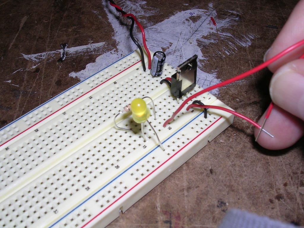
The first step was to build a simple circuit with a 7805 regulator, a 220 ohm resister, an LED and a switch. The challenge was to remember what the components looked like, and and how to read their ratings. Not having a switch, I used two pieces of wire (you can see them on the right side of the photo).
The second step was to build a series of LEDs. I was able to get two to work... kind of. Adding a third killed the whole thing, though. The odd thing is, with two, my LEDs blinked. Swapping out a yellow LED for a red one caused the blinking rate to change, but didn't stop the LEDs from blinking. Todd took a look, but couldn't find any fault in my wiring set up. The only variable in the system was my power supply. Exchanging it for a new one did the trick. I have a feeling that the power supply I brought in is just barely putting out 5v.
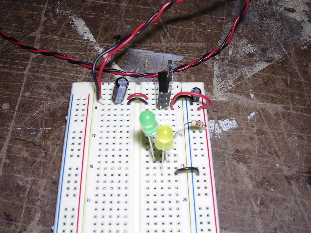
The remaining steps were rather uneventful: no blinking LEDs, nothing caught fire, no one had to kick me clear when it arc'ed, but I still had fun. I built a circuit that had three LED's in parallel, and one with a variable resistor photo cell. Covering the photo cell didn't have a huge impact on the brightness of the LED; however, placing a light source on it caused the brightness to go way up. The photo below shows the parallel and variable circuits.

posted by Terence Arjo @ 3:30 PM
![]()

<< Home